Best Tips About What Are The 7 Types Of Lines In Technical Drawing Excel How To Add Vertical Line Chart
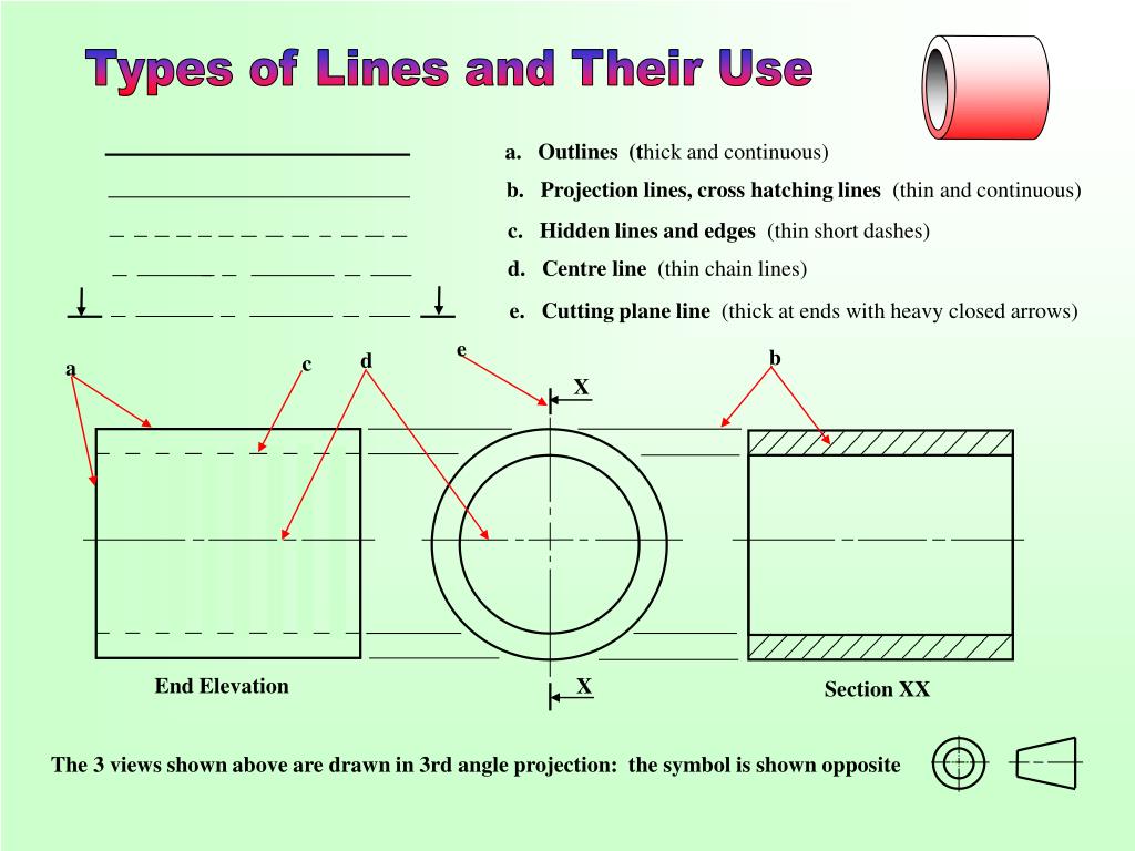
Technical drawing lines are used for different purposes to provide specific information for designers, manufacturers, etc.
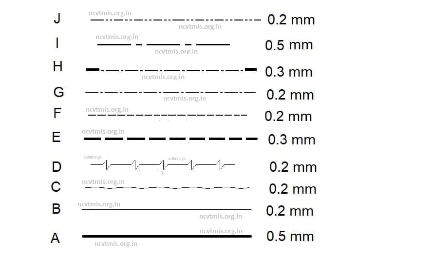
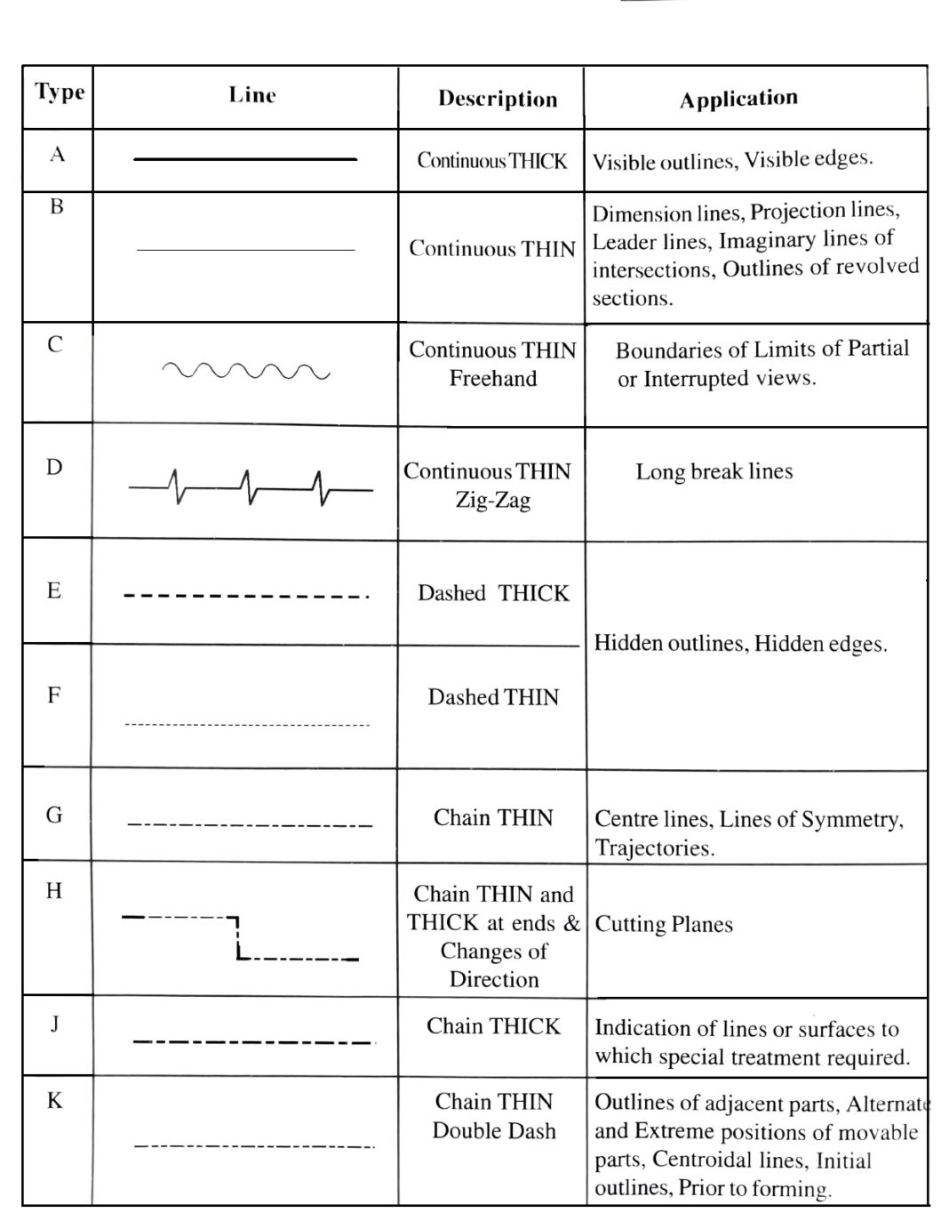
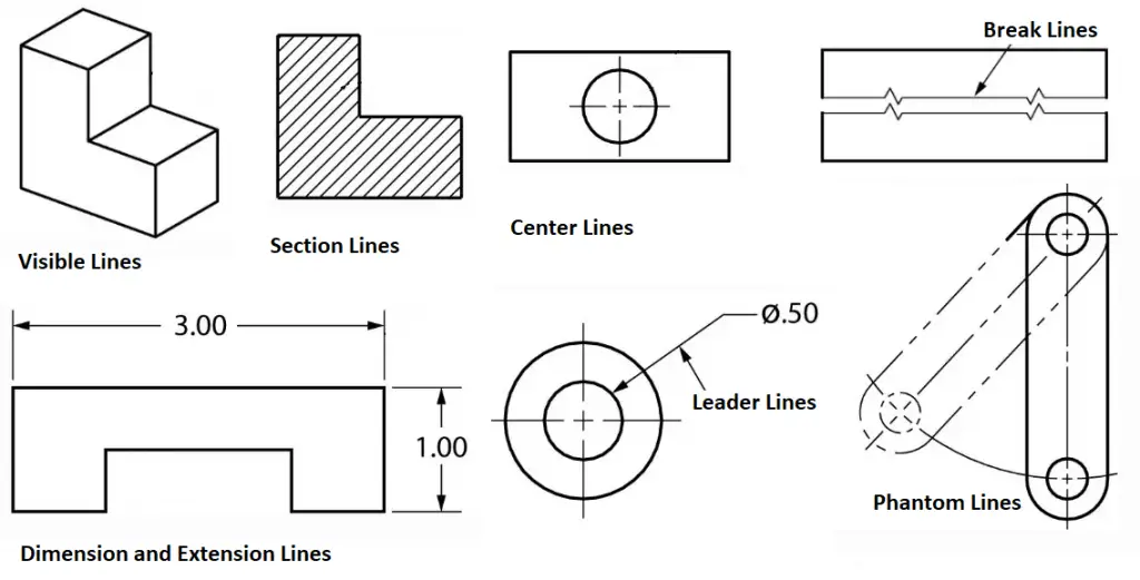
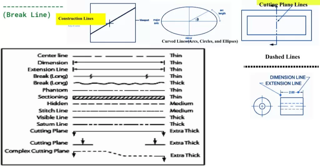
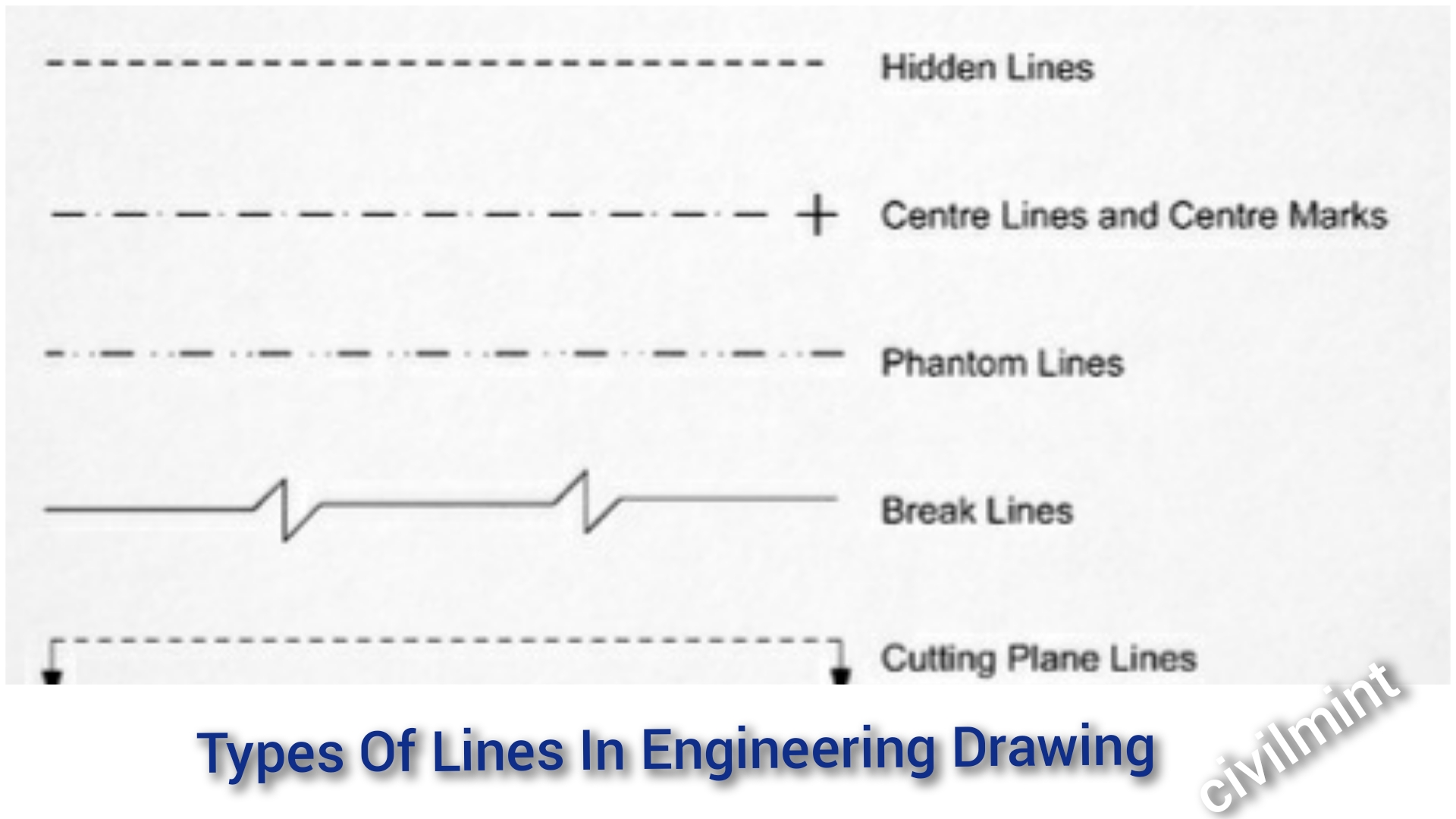
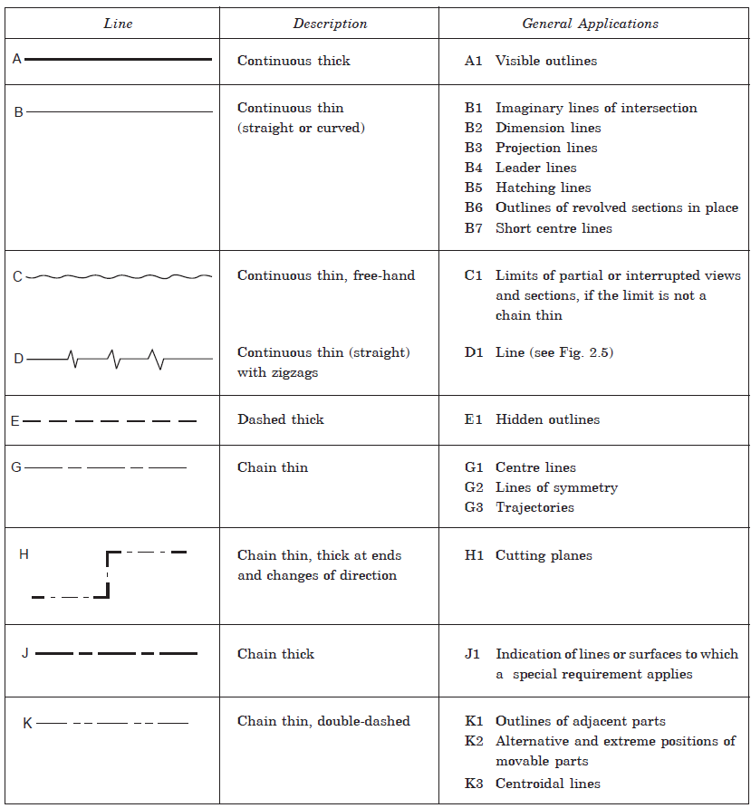
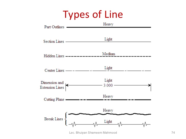
What are the 7 types of lines in technical drawing. Thin lines are hidden lines, center lines, section lining, phantom lines, extension lines and dimension lines. In this detailed guide on different types of lines in engineering drawing, we will discuss line types, their designation, configuration, and general drafting Section lines (hatching) are used in section views to represent surfaces of an object cut by a cutting plane.
They are dark and thick lines of any. [faq] when you begin to learn drafting, you have to learn about the different types of lines. A section line is a.7 mm to.9 mm line drawn at angles, normally 45, 30 or 60 degrees, to show a feature more clearly.
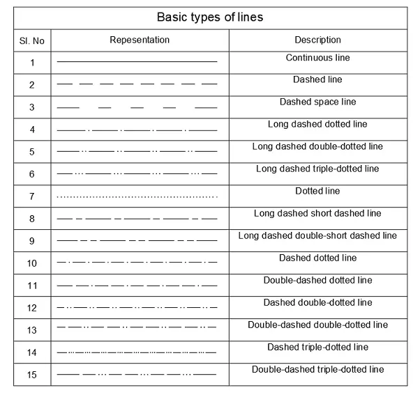
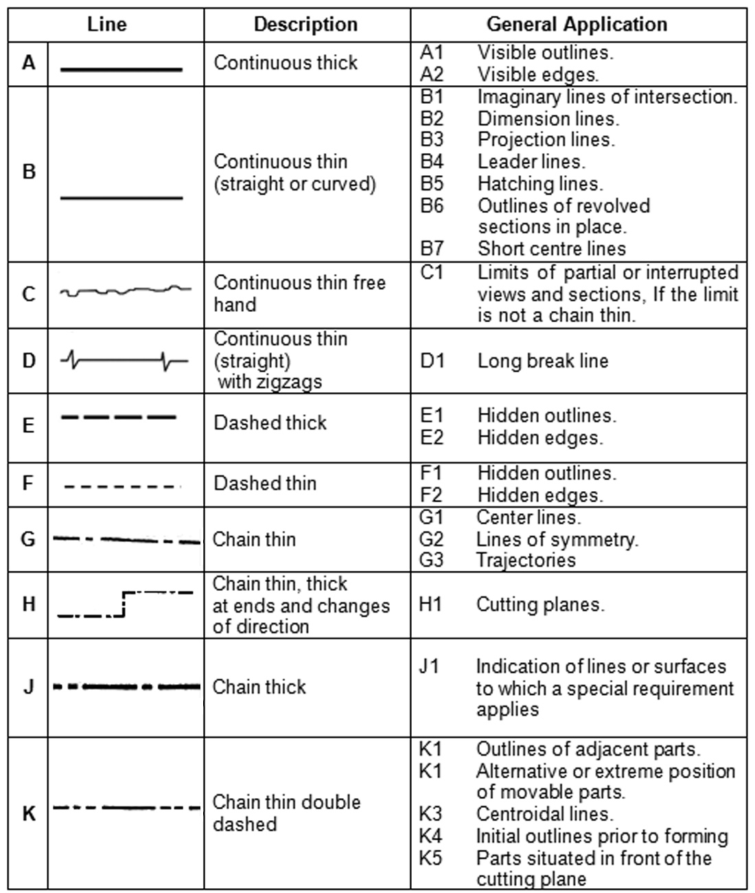
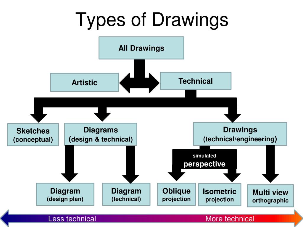
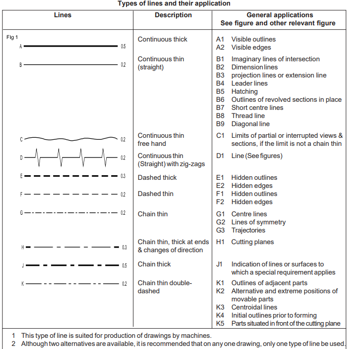
Drawing are types of diagrams used for communication to show the shape and structure of a given idea or product. The diagram below shows the various types of line, their description and general application: Mastering the various types of lines is essential for precision and clarity in engineering drawings.
The cutting plane line is a.5 mm dashed line with arrows on the end to show where it. In the design industry, there are standardized line types and correct techniques to be used for producing professionally hand drafted drawings. Certain features on a engineering drawing requires specific ways of indication.
Identify line types used in technical drawings; Each type of line has a very precise symbolic meaning. We’ll look at the different parts of these drawings, like the kinds of lines used and the different views (like looking at something from the top, side, or front).
Hidden detail are shown with a certain line type to avoid confusion with visible edges. Technical fields use drawings to draw designs of different items before they are made. Two dimensions (2d) and three dimensions (3d).
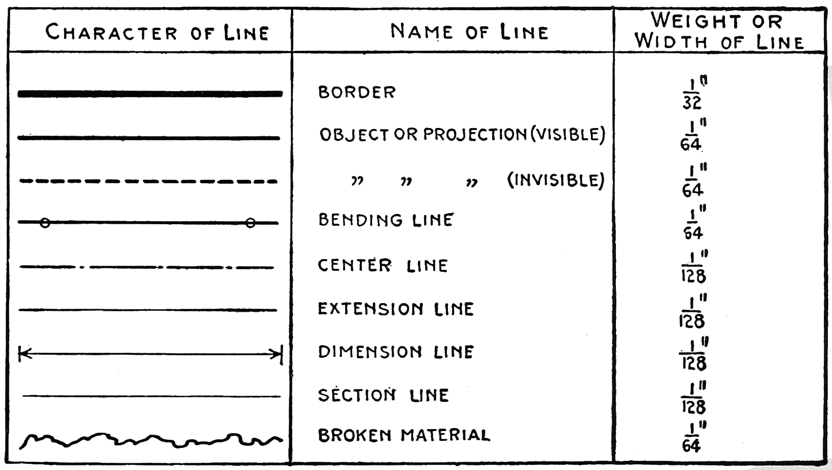
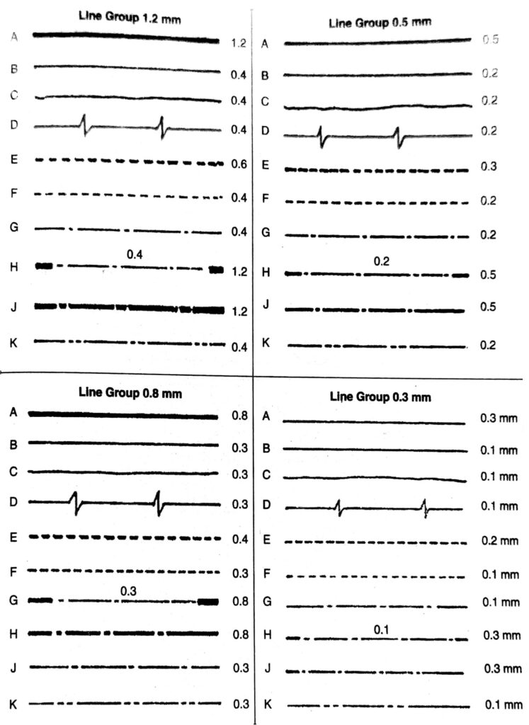
In order to convey that meaning, the lines used in technical drawings have both a definite pattern and a definite thickness. Some lines are thick, and others are thin. Some lines are complete, and others are broken.
For example, holes require center lines to identify the center and show that it is round. Twenty types of technical drawing lines and their respective uses are as follows: Here are the key types of lines you’ll encounter.
Types of lines for technical drawings. Dimension and extension lines are used to indicate the sizes of features on a drawing. All lines on a drawing should be black regardless of the thickness.
Phantom lines are used to represent a movable feature in its different positions. These different types of lines serve specific purposes in technical drawings and are essential for conveying accurate and detailed information in engineering, architecture, and design. Type of lines.
